






Industrial Ventilation System Design with Integrated Dust Collection
Industrial ventilation systems with integrated dust collection represent essential engineering controls for maintaining workplace air quality, ensuring regulatory compliance, and protecting worker health across manufacturing, processing, and material handling operations. These comprehensive systems, designed and manufactured by specialized environmental engineering companies, require careful coordination of capture hood design, duct network sizing, air cleaning device selection, and fan system specification to achieve optimal performance at reasonable capital and operating costs.
Capture Hood Design Principles and Efficiency
Effective dust capture begins with properly designed hoods that generate adequate capture velocities at dust generation sources. The hood type—enclosing, receiving, or capture hood—depends on process configuration, dust generation mechanism, and practical constraints including access requirements and material flow patterns. Enclosing hoods, completely surrounding the dust source, achieve highest control efficiency with minimal exhaust airflow, while open capture hoods require higher capture velocities (typically 100-200 fpm) to overcome cross drafts and thermal updrafts.
Hood design must account for process equipment dimensions, material trajectory, thermal plumes, and cross-draft interference. Computational fluid dynamics (CFD) modeling, employed by experienced ventilation system suppliers, predicts airflow patterns and capture efficiency for complex hood configurations, enabling optimization before capital commitment. The hood's aspect ratio, slot opening dimensions, and plenum design influence static pressure losses and flow distribution, factors that reputable manufacturers evaluate during the design phase to ensure uniform capture along extended sources.
Ductwork Sizing and Pressure Loss Management
Ductwork design balances capture hood requirements, transport velocity needs, and system pressure loss limitations. Transport velocity—the minimum air velocity required to maintain particulate suspension—typically ranges from 2,500 to 4,000 fpm depending on particle size, density, and adhesive characteristics. Undersized ducting causes particle settling and duct plugging, while oversized ducting wastes fan energy and increases capital costs.
Pressure loss through duct networks comprises friction losses (function of duct length, diameter, and airflow velocity) and dynamic losses (fittings, transitions, elbows). The Darcy-Weisbach equation or empirical friction charts predict straight duct losses, while loss coefficients (C-values) quantify fitting pressure drops. Modern duct design software, utilized by professional ventilation system integrators, calculates system pressure loss, optimizes duct diameters, and balances branch airflows through damper adjustments or duct resizing to achieve uniform capture across all hoods.
Fan Selection and System Performance Curves
Fan selection must satisfy both airflow volume and static pressure requirements while operating efficiently within the system curve. Centrifugal fans (backward-inclined, airfoil, radial) suit high-pressure applications typical of ducted dust collection systems, while axial fans serve low-pressure, high-volume applications such as building ventilation. The fan's operating point—intersection of fan performance curve and system resistance curve—must fall within the fan's stable operating range and avoid resonance regions that cause excessive vibration or noise.
Variable frequency drives (VFDs) enable fan speed control to match actual capture requirements, reducing energy consumption during partial load operation. VFD control also facilitates system balancing, soft starts, and integration with process interlocks for safety and energy optimization. Leading ventilation system manufacturers provide fan performance curves, system effect factors, and VFD sizing recommendations to ensure reliable, efficient operation across all operating scenarios.
Integration with Air Cleaning Devices
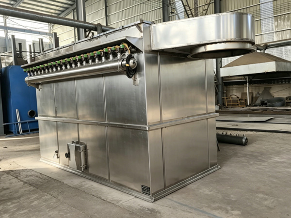
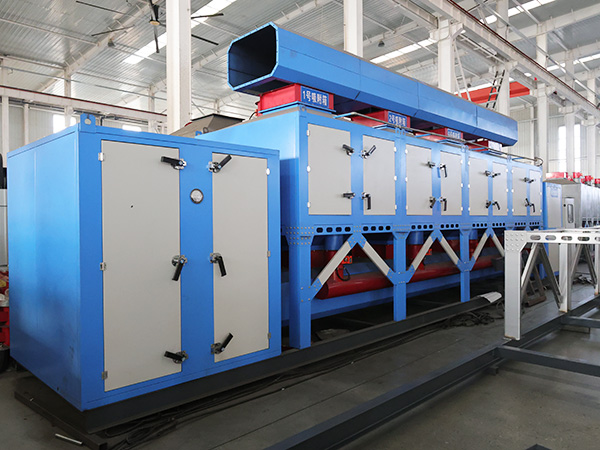
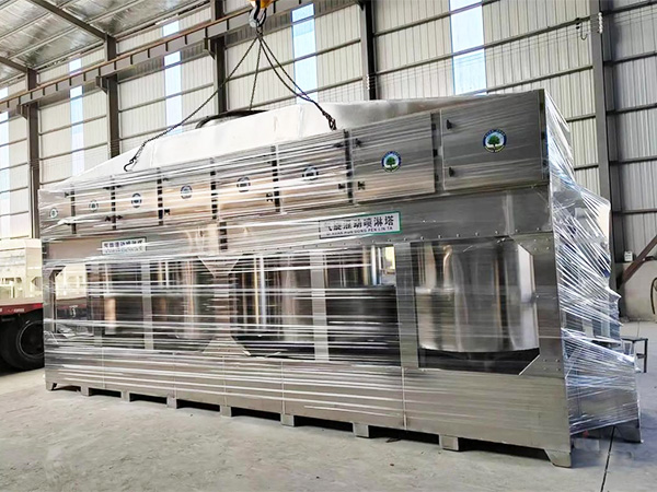
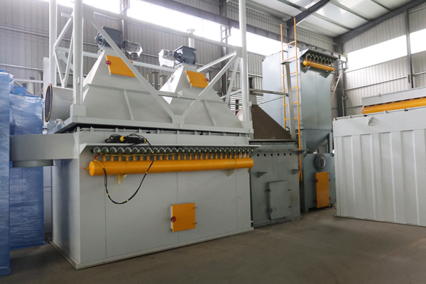
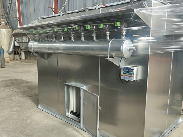
The ventilation system's air cleaning device—baghouse, cartridge collector, cyclone, or wet scrubber—must accommodate design airflow with acceptable pressure drop while achieving required emission limits. The cleaner's location (upstream or downstream of the fan) influences fan selection, materials of construction, and maintenance access requirements. Upstream fan placement protects the fan from abrasive dusts but may require erosion-resistant fan construction, while downstream placement subjects the fan to clean air but necessitates explosion-proof or spark-resistant construction for combustible dust applications.
System balancing between multiple hoods, cleanouts, and air cleaning devices requires careful consideration of pressure drops, duct configurations, and process variability. Blast gates, variable position dampers, or automatic flow control devices maintain designed airflows despite process changes or system modifications. Professional ventilation system suppliers provide balanced design documentation, installation supervision, and commissioning services to verify that actual system performance matches design intent.
References
ACGIH Industrial Ventilation: A Manual of Recommended Practice, 30th Edition
ASHARE Laboratory Design Guide
OSHA 29 CFR 1910.94 - Ventilation
NFPA 68 - Standard on Explosion Protection by Deflagration Venting
ISO 29463 - High-efficiency filters and filter media against particles